
DOWNLOAD THE APP


Customer Services
Copyright © 2025 Desertcart Holdings Limited
DOWNLOAD THE APP


💥 Light Up Your Skills, One Solder at a Time!
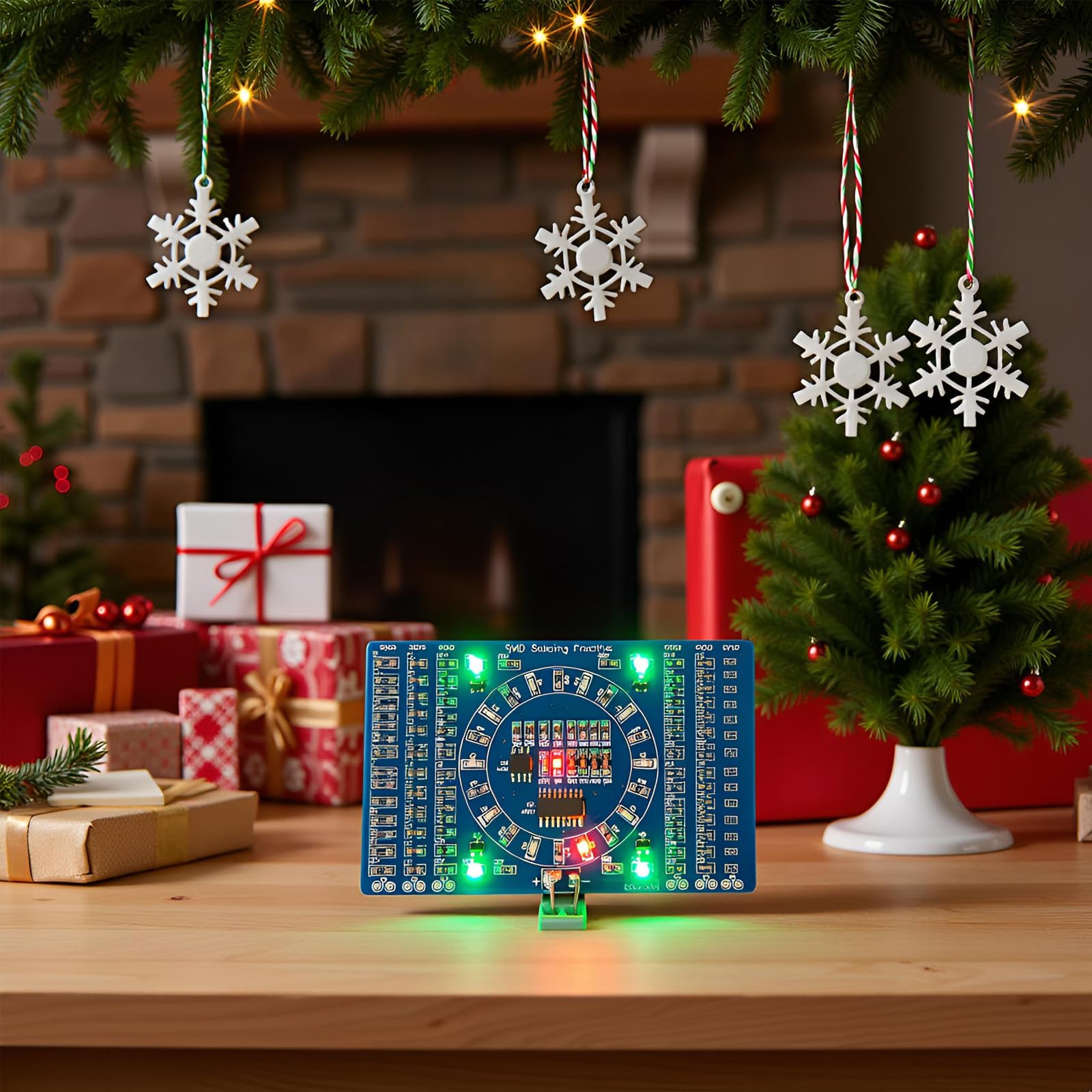
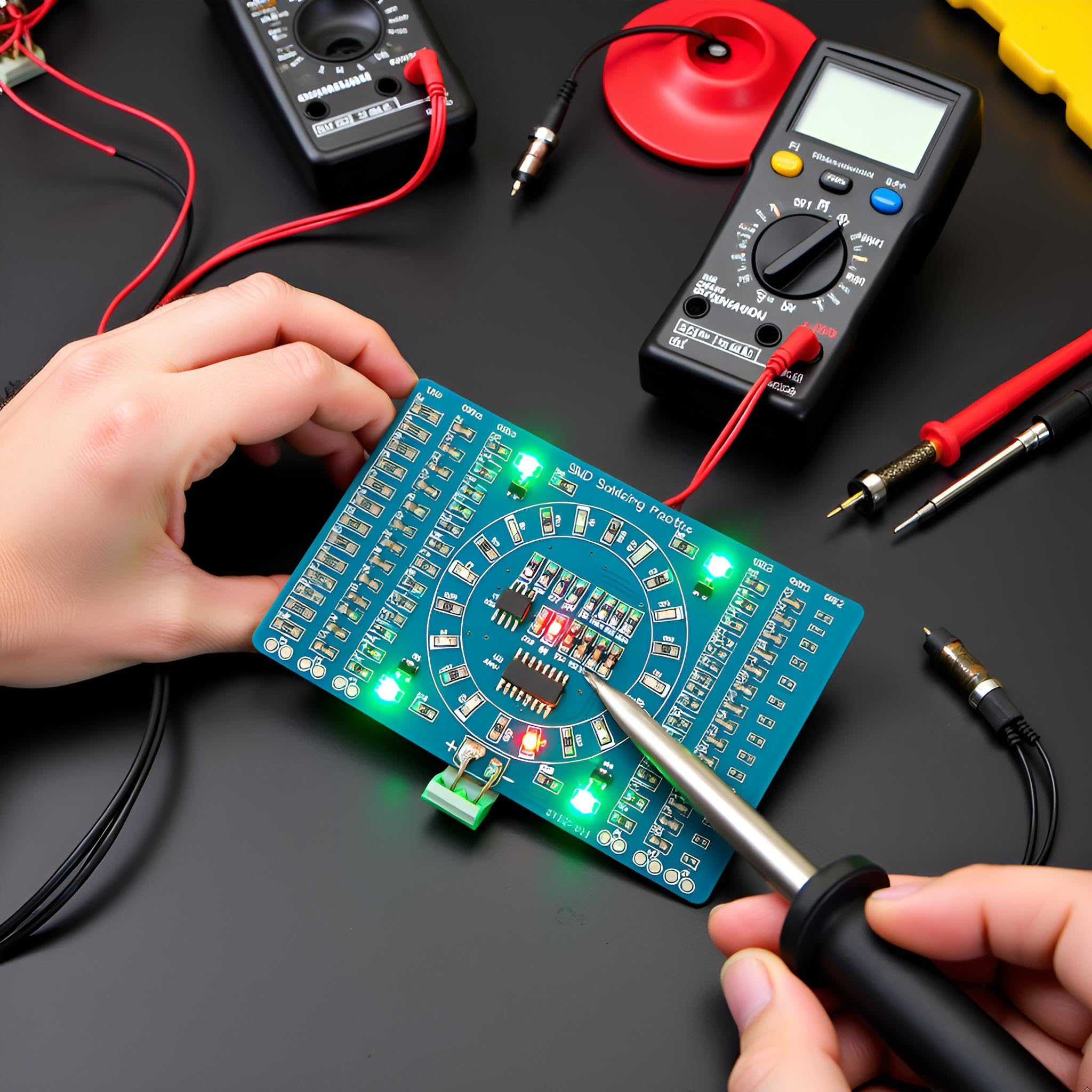
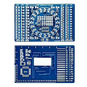
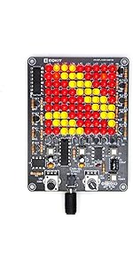
The Gikfun Soldering Practice DIY Kit EK7026 is a beginner-focused, dual-sided PCB training board designed to sharpen your SMD soldering skills. Featuring four common SMD component sizes, a built-in LED chase circuit powered by 3-12V, and precision rulers on the back, it offers instant visual feedback and practical measurement tools. Ideal for millennial professionals eager to upskill in electronics, this compact kit combines hands-on learning with satisfying, real-time results.


| ASIN | B00Y20JYTM |
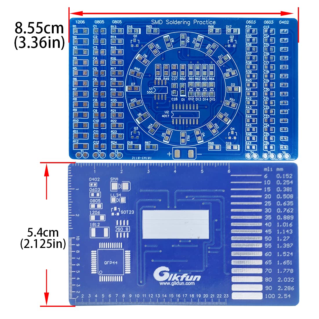
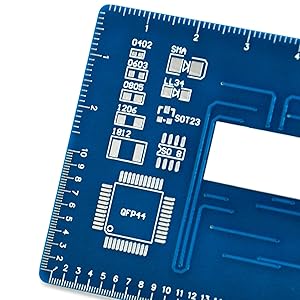
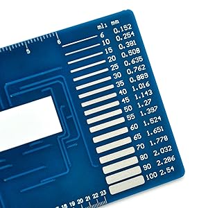
| Additional Features | Back of the board with mm/Inch ruler, Dual-sided PCB welding, English user manual and online PDF file, Specially designed SMD soldering practice board |
| Aspect Ratio | 4:3 |
| Best Sellers Rank | #177,826 in Automotive ( See Top 100 in Automotive ) #2,093 in Welding Equipment & Accessories |
| Brand | Gikfun |
| Built-In Media | SMD Components |
| Color | blue |
| Connectivity Technology | LAN |
| Customer Reviews | 4.3 out of 5 stars 485 Reviews |
| Display Resolution Maximum | 3840 Pixels |
| Display Type | LED |
| Graphics Card Description | Dedicated |
| Graphics Card Interface | Integrated |
| Graphics Description | Dedicated |
| Graphics Ram Type | Unknown |
| Hard Disk Interface | SATA 3 GB/s |
| Hardware Interface | USB |
| Human-Interface Input | Numeric Keypad |
| Item Dimensions | 5.3 x 0.4 x 3.4 inches |
| Item Weight | 22.68 g |
| Keyboard Description | Keyboard with numeric keypad |
| Keyboard Layout | QWERTY |
| Manufacturer | Esooho |
| Memory Slots Available | 1 |
| Model Name | LYSB00Y20JYTM-ELECTRNCS |
| Model Number | LYSB00Y20JYTM-ELECTRNCS |
| Native Resolution | 3840 x 2160 |
| Number of Component Outputs | 1 |
| Personal Computer Design Type | Computer Tower |
| Personal computer design type | Computer Tower |
| Power Plug Type | No Plug |
| Processor Brand | Intel |
| Processor Count | 1 |
| RAM Memory Technology | DDR4 |
| RAM Type | DDR4 SDRAM |
| Resolution | 3840 x 2160 |
| Screen Size | 3.36 Inches |
| Specific Uses For Product | Education |
| Total Usb Ports | 1 |
| UPC | 634894432564 728821647494 |
| Video Output | VGA |
| Video Output Interface | VGA |
| Video Processor | Intel |
A**O
Great SMD Practice Kit
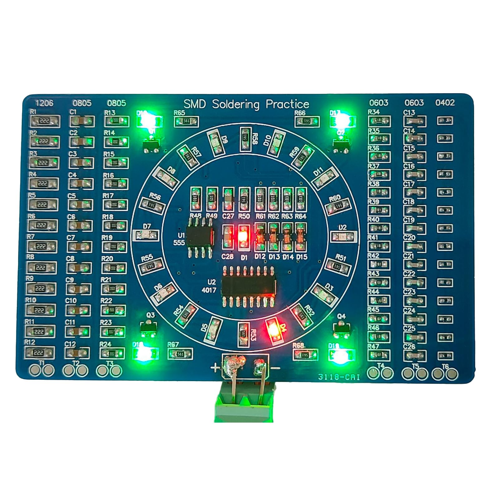
DESCRIPTION: The description is somewhat lacking, so I'll try to clear up some of the confusion. This is a beginner SMD soldering kit, intended for practice. It includes two "sections" on the front of the board: practice and an LED circuit. The back contains several rulers in standard and metric, a trace-width gauge, and standard SMD component pad patterns for reference. The first section is is a practice area for various surface mount components, and consists of the three vertical rows on each side of the board. These rows consist of solder pads for four different sizes of SMD parts: 1206, 0805, 0603, and 0402 (Google "SMD sizes" to find out what those numbers mean if you don't already know). The kit includes resistors and capacitors to solder to these rows, and I believe the values are random. These rows aren't electrically connected to the LED circuit, so it's fine if you make mistakes or lose components. They even include a few extra of each, which was good because I managed to lose a few of the 0402 resistors when they slipped out of my tweezers. Those things are TINY. The second section is the actual LED circuit, and it's located in the center of the board between the two groups of practice rows. It consists of a 4017 decade counter which drives a ring of red LEDs. The LED's light one at a time, chasing around the circle. Four blue LEDs at the corners of the center section pulse on and off together once per revolution (on for half, off for half). A 555 timer provides the pulses to drive the counter, and also illuminates a red LED in the center of the circle with each timing pulse. The circuit incorporates several SOT23 transistors and DO diodes. The ICs are both SOIC packages. The speed and brightness of the LEDs will depend on the input voltage you apply. ASSEMBLY: I don't think I could have done this without a good pair of tweezers, some form of hands-free magnification (I love my Brightech - LightView PRO SuperBright 56 LED Magnifier Lamp - Adjustable Swivel Arm - 5 Diopter 5" Lens - Space Saving Clamp - White ), and a fine-tipped soldering iron. Having the right tools for the job is a huge advantage. My instructions were in English, but not as clear as I'd like. First I separated all the components into the two groups, one for each section (the practice parts and the "real" LED circuit). The component values for the LED circuit are shown on the instructions. They should all be pretty obvious because there are small numbers of most of them. The only confusing one was the strip of 330-Ohm resistors. Make sure you put the strip of resistors marked "331" in the LED circuit pile. After separating the LED circuit parts, you should have 6 leftover strips of resistors and capacitors. These leftover strips should have about 14 components each of the 1206s and 0805s, and about 16 each of the 0603s and 0402s. Start with these and practice your technique. It's probably easiest to start with the larger components and work your way down to the smaller ones. Search online for SMD soldering tutorials if you need to. Once the practice rows are done, you should be ready for the main circuit. The trickiest part is the polarities of the diodes. Use the picture guide in the instructions and note that the LED polarity symbol is on the underside of the part. For the ICs, solder one corner first, then the opposite corner to hold the part steady. Then solder the rest of the pins. If you accidentally connect two pins, use some solder wick to mop up the excess solder. The wick won't pull the solder from between the IC and the board, so you can make a really clean-looking connection this way. Lastly, check that power is not shorted to ground (use the continuity mode on your multimeter and test the positive and negative terminals at the bottom of the board). Then hook up the power! I used some alligator clips and a 9v battery (I believe 3V to 12V is recommended). This was my first SMD project and if I figured it out, you probably can too. If you have any questions, leave a comment and I'll do my best to answer you quickly. Have fun!
H**E
Second time's the charm
If you're considering this to try SMD soldering, I strongly recommend you have a soldering station, one that has a programmable temperature, and a microscope. Read my experience with this kit below, and you'll see I did it with a magnifying headband. It's possible but a microscope will make this project so much more bearable. Just be sure the microscope head is far away enough from the board that you can get your soldering iron in there! I bought the red version of this last year and ruined it completely; I tried soldering the components roughly the same way I'd solder THT (Through hole) components. The tiny components in the kit stuck to my iron, or I took so long trying to solder them to a pad I'd completely fry them. I managed to get a bit of formal SMD soldering training in at work, and I studied on techniques. I decided to try this blue version out to try my skills again. This one turned out better, and the functional LED circuit works. This kit is a heck of a workout if you don't have a microscope though! I used a jeweler's headband magnifier, which goes to 10x magnification. That level felt like the bare minimum to my eye, any lower magnification power and I couldn't clearly see what I was doing. But since I was wearing a head band to see, I had to slump forward over my rolling workstation toolbox to get in focus. So, if you don't have a microscope, use a headband like I did. An eye loupe will place your face dangerously close to the soldering iron, and you could get solder spatter in your other eye. Even with my headband, I got a few breaths of soldering fumes, so again, a microscope with enough clearance for your soldering iron to get under is very strongly recommended! I sorted out the components by reading the values on the resistors and comparing the quantities of components that came with the kit to the materials and supplies list that came with the instructions, which have hastily scrawled instructions for SMD soldering but little instruction on how to assemble this kit. Once I got everything sorted out, I soldered the "extra" components on the practice areas. There are a lot of pads, so you'll get PLENTY of practice here. I then went on to solder the components to functional part of the board, soldered lead wires to the + and - pads, and voila! My project lit up! The finished product is simple in aesthetics and function, so only the individual that solders this kit together is going to get any enjoyment out of watching this light up. So I would only recommend this kit if you want a solid amount of SMD soldering experience outside of formal training. With the right equipment and experience, this kit isn't horribly difficult, but I wouldn't call it easy either!
J**0
Good practice, instructions poor.
Instructions poor. Parts not marked or not marked well, have to match up quantities in package with BOM. Only way to assemble is making a screen shot printout of the Amazon listing photo. Other than that, if you figure it out, the project works when assembled. I used solder paste and hot air to assemble. Gave very good practice on SMD soldering. Extremely easy to lose parts, they are incredibly tiny. In some cases there is an extra part supplied. Most cases not, be careful.
S**M
Good Entry level board, but need the right equipment.
This Kit is a challenge. Not for the faint of heart. If you are developing the skill of soldering SMD parts, it is very helpful. I wondered if I could do this kind of thing. At 57 my eyesight is not what it used to be. But with the right tools, you can do it. I bought an Ex-tronic soldering station, the ability to control temps and pick the right tip is nice. I got a lighted magnifying glass with the solder station, worked great. Get a very good set of Tweezers. You need very small diameter of Solder, .8 - .5. Probably the smaller the better. The Product comes with limited instruction, and the parts don't match well. You need some added information you must supply. If you are at the level of developing this skill, this entry level practice board works well.
S**.
Not bad, but instructions need work ...
This kit is for practicing soldering SMD components. The instructions I got had a circuit schematic and a list of parts included (many were assigned "RANDOM" values). You have to count the particular type of parts and use their relative size to gauge what is what, which can be a bit confusing. I guess the manufacturer assumes you know enough about circuits and such. The practice columns have test points so you can check most soldered parts with a multimeter. I say most because the 0402 column was wired for resistors (in series) but I got capacitors (which need to be in parallel for it to work). But you can still use the continuity tester and capacitance mode on a lot of meters. I had no problems or issues getting the LED circuit to work using a standard size Hakko chisel tip and 1.0mm 60/40 Radio Shack Rosin core solder. I see some reviewers had red and blue LEDs. Mine were red and green.
A**S
Not your first soldering kit, but your first Surface-Mount kit.
I had a lot of fun putting this together. Pictures as follows: 1. First component soldered in place, 10 days after buying the kit. 2. Second component, another 3 days later. I'm not fast. 3. Starting to identify the components, realising the left-hand columns are non-functional, for-practice only. 4. The three left-hand columns are all complete. Definitely needed the angle-ended tweezers to accomplish this. 5. More component identification, and the chips are soldered in place. 6. The component that fell on the floor, white-side up, and was sooo hard to find. Don't sneeze! 7. All components in place, but only one LED lights up. No motion suggests the timer IC (555) needs to be retouched. 8. Video now that there's movement - but several lights are not lighting. Checked the circuit diagram to see which pins of the larger IC feed those LEDs, and retouched those pins (D6 = pin 10; D10 = pin 9; D11 = pin 11; D16-19 = pin 12). Very proud of having put this together (I skipped the 0402 components, because they're just stupid tiny). I can now view SMD component kits as "something I can do". Following simple circuit diagram to decide which pins must be badly soldered is a new skill, and so I've explained it a little with the descriptions of the images above. If you are looking for a first kit to learn surface mount soldering, this is a really good kit for that purpose. Don't do this if you haven't done some through-hole soldering already, because SMD is way more fiddly, and prone to errors.
J**N
Mostly a good experience.
I have not quite finished putting it together yet, but I finished each of the six outside rows. Well. I finished 5 of the 6. I bought to teach myself SMT soldering, as all my prior experience was with thru-hole parts. A few fairly complicated projects since college, a theremin kit, a tube amp (from scratch). I’m looking forward to finishing this up tomorrow. Specifically I’m looking forward to not having to try any more of those 0402 1x0.5mm parts. It’s hard to believe but even the 6x3mm resistors and caps were pretty easy; little blob on one pad, grab the part w tweezers, melt the blob, hold the part in place with tweezers, lift the iron, hold a couple seconds, lift the tweezers. The 0402s? Complete nightmare. If I had some more to try, I might try washing the tweezers in alcohol, getting a blob of solder on the iron, holding the part in place, touching one pad&end of one resistor for a couple seconds, then lift the iron, hold the part a few seconds, then lift. The problem with doing it with the blob of solder already on the pad is that there is flux. The part is so small that even if you wipe off the tweezers, you will get residual flux on the tweezers, and the surface tension of the flux on your tweezers is enough to pull the tiny component out of the molten solder. Maybe you could wash the flux off the board with a q-tip and some alcohol. A few ideas that I have, now that I have horked up the 0402 components. But you know what? I’m NEVER going to use 0402 components, and all the rest were easy! I hope I have as good luck with the ICs and transistors and diodes.
E**.
Good for learning hot air soldering.
I have never had good luck hand soldering SMD components. Hands are too shaky and eyes are too bad, in other words I'm getting too old. I have successfully built a couple of projects using SMD and soldered by hand but was never happy with the results, so I bought a hot air soldering station and bought a couple of these practice kits to learn. They worked out like a dream. Successfully built both kits and learned a lot, and more importantly got the confidence that I could do this kind of work given the right tools. The only problem I have with this kit is that the documentation is not the best, and none of the parts are labeled. The IC's are easily identifiable by shape, but the resistors and capacitors are not. Overall a good kit to learn SMD soldering with an iron if you have the steady hands and eye sight, or, if you're like me, and decide to cheat by using a hot air station. Just be prepared to figure out what the components are with out any documentation.
Trustpilot
1 month ago
1 month ago